PTO Speed Reduction Unit

This project involves designing a PTO speed reduction unit to transfer power from a 45kW diesel engine to a hydraulic pump, reducing speed from 2800 rpm to 1300 rpm with a gear ratio of 2.15. Using durable materials like EN24 and EN8 steel, the unit ensures longevity and ease of maintenance. It’s designed for efficient power transfer, minimal wear and straightforward assembly, making it suitable for large-scale production. The PTO unit combines performance and durability for effective power transfer.

Project Overview

Our team designed a PTO (Power Take-Off) speed reduction unit to bring a 45kW diesel engine’s speed from a whirlwind 2800 rpm to a steady 1300 rpm, making it perfect for powering hydraulic systems. The goal? Reliable performance with durability and easy upkeep.

  • Gear Ratio: We used a 2.15:1 gear ratio to expertly slow things down, ensuring smooth power transfer.
  • Built to Last: Gears made from EN24 and EN8 steel are designed to keep going strong for up to 20,000 hours. Meanwhile, the shafts—crafted from medium-carbon steel—can handle the load.
  • Casing: The lightweight cast-iron casing keeps everything cool and protected, offering durability without adding bulk.


Maintenance? Piece of Cake.
With this PTO unit, maintenance isn’t something you dread—it’s part of the fun! We designed the unit with user-friendliness in mind, so there's no need for complicated tools or an engineering degree to keep it running smoothly. A simple oil change every 2500 hours, a bit of greasing here and there, and this unit will keep humming along happily. It's like the car maintenance version of “set it and forget it,” but for industrial machinery.

And of course, here is why you'll love our PTO:

  • Efficiency: Perfect for large-scale production or as a reliable partner in any industrial setup.
  • Cost-Effective: Low production costs paired with high performance.
  • User-Friendly: Easy assembly, low maintenance, and reliable operation.


This PTO speed reduction unit offers reliable power transfer, long-lasting durability and easy maintenance—all while making your life a little easier.

Softwares and Tools Utilised

Icon
Weeks 1-2
Research and Specification Development

My team focused on understanding the project requirements and defining the specifications for the PTO speed reduction unit. This included setting performance goals to reduce the engine speed from 2800 rpm to 1300 rpm using a gear ratio of 2.15, and selecting durable materials like EN24 and EN8 steel for the gears.

Icon
Weeks 3-4
Gear Design

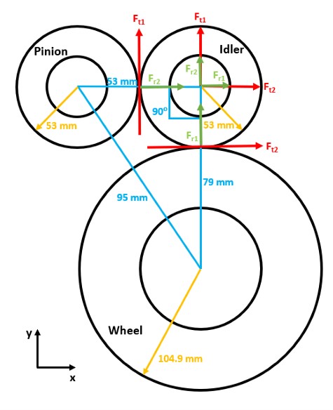
The gear design took center stage. My team calculated gear ratios and torque requirements, utilising GP100 software to ensure the gears were designed for optimal performance and longevity. An analysis of power transfer efficiency and load distribution was also conducted.

Icon
Weeks 5-6
Shaft and Bearing Design

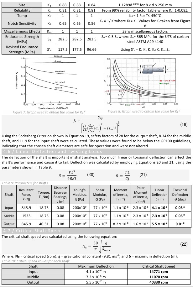
Attention shifted to the shafts and bearings. Medium-carbon steel was selected for the shafts due to its strength, and a comprehensive fatigue and stress analysis was performed to ensure they could withstand dynamic loads. Bearings were also carefully chosen based on their load capacity to ensure smooth, long-term operation.

Icon
Weeks 7-8
Validation and Maintenance Planning

The validation phase began, where calculations were finalised to confirm that the PTO unit met all performance goals. Additionally, we focused on the ease of assembly, minimising the need for special tools to keep the process user-friendly.

Icon
Weeks 9-10
Initial Assembly Drawings

My team then began producing the assembly drawings, detailing key components such as the gears, shafts and casing. We worked on ensuring that the layout and arrangement of parts would allow for seamless assembly.

Icon
Weeks 11-12
Final Drawings and Exploded Views

The drawings were completed with detailed exploded views, showing the arrangement of all internal components. These final drawings included material specifications, tolerances and assembly instructions, all aligned with industry manufacturing standards.

Now that we’ve cruised through the timeline, let’s dive into the design report—where the gears start turning, and the engineering brilliance really kicks into high gear.

Design Report

Weeks 1-8

Gear Design:

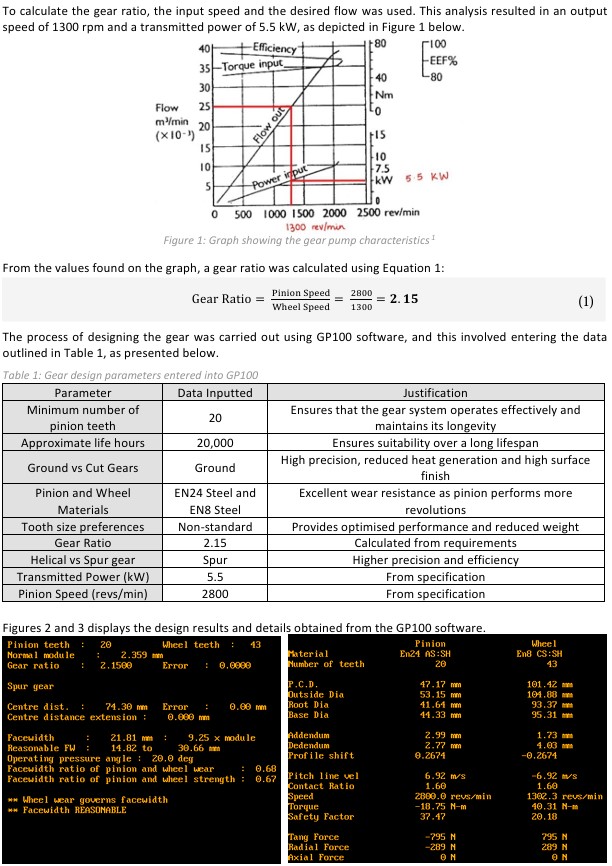
When it comes to gear design, it's all about turning that engine power from a 2800 rpm sprint into a smooth, manageable 1300 rpm jog—thanks to our perfectly calculated 2.15:1 gear ratio.

We didn’t just grab any old gears off the shelf. These are made from EN24 steel for the pinion and EN8 steel for the wheel, because durability is key when you’re dealing with the kind of power that could easily turn metal into mush.

Using GP100 software (and a few cups of coffee), we crunched the numbers on everything from the number of teeth to the perfect tooth size. The result? Gears that are tough enough to handle anything, while staying cool under pressure. And they’ll keep turning smoothly for up to 20,000 hours.
Shaft Design:

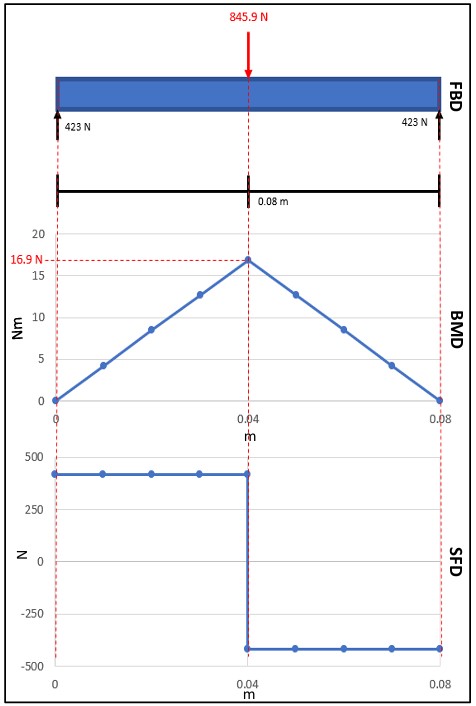
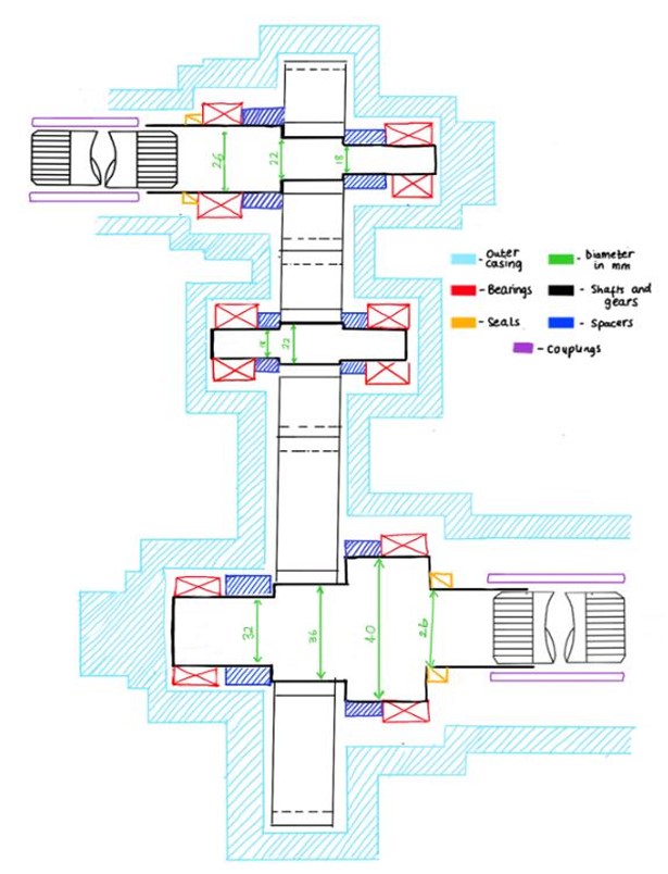
Our shafts, made from tough ASTM A29 4140 medium-carbon steel, were designed to handle everything from bending moments to torque. Precision-calculated for strength and durability, these shafts ensure smooth power transfer, keeping everything running steady and strong—no wobbles, just results.

Interfacing:

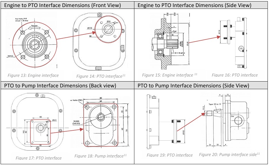
Connecting the engine, PTO unit and pump wasn’t just about bolting things together—it was all about precision.

Standard dimensions and bolt threads ensured the parts fit together, reducing any chance of a misstep.

The interface design made it easy for maintenance and replacement, while ensuring perfect alignment so everything runs smoothly, without any awkward wobbles or breakdowns.
Assembly and Design for Assembly:

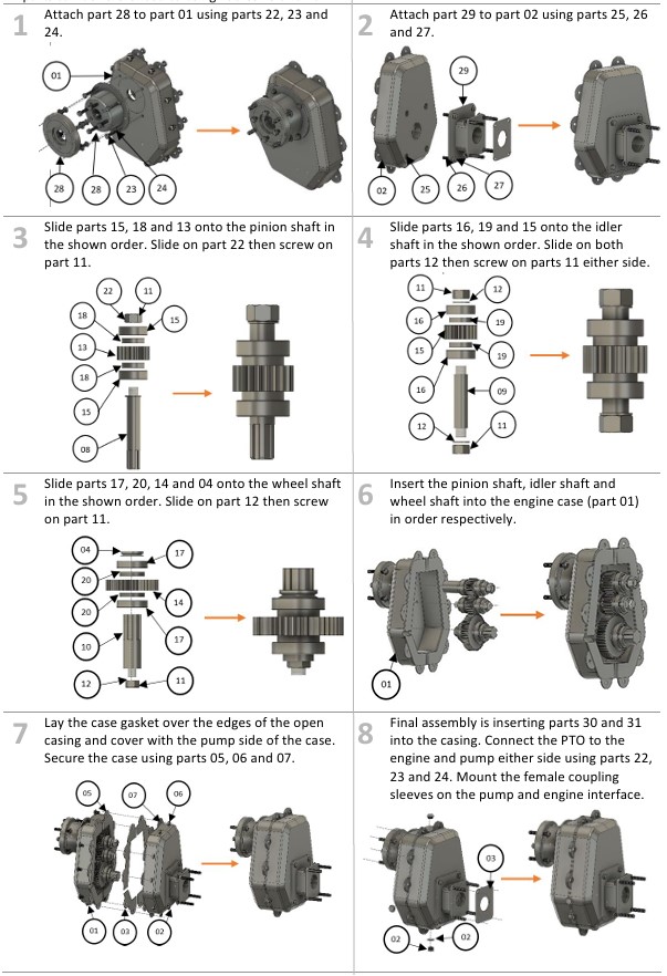
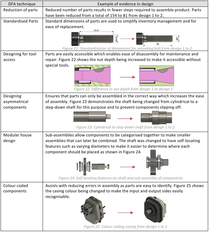
When it comes to putting the PTO unit together, simplicity was key. We designed everything to fit like a puzzle—fewer parts, standardised shapes and easy access for tools meant less frustration and faster assembly.

Our modular sub-assemblies slotted together perfectly, with colour-coded components to keep even the most distracted assembler on track.

By focusing on tool accessibility and self-aligning features, we made sure that anyone could assemble (and disassemble) the unit without needing a PhD in mechanical engineering—or a magic wrench.
Final Design:

With the design all mapped out, it’s time to see how it comes together—welcome to the assembly drawings, where every nut and bolt finds its perfect place.

Assembly Drawings

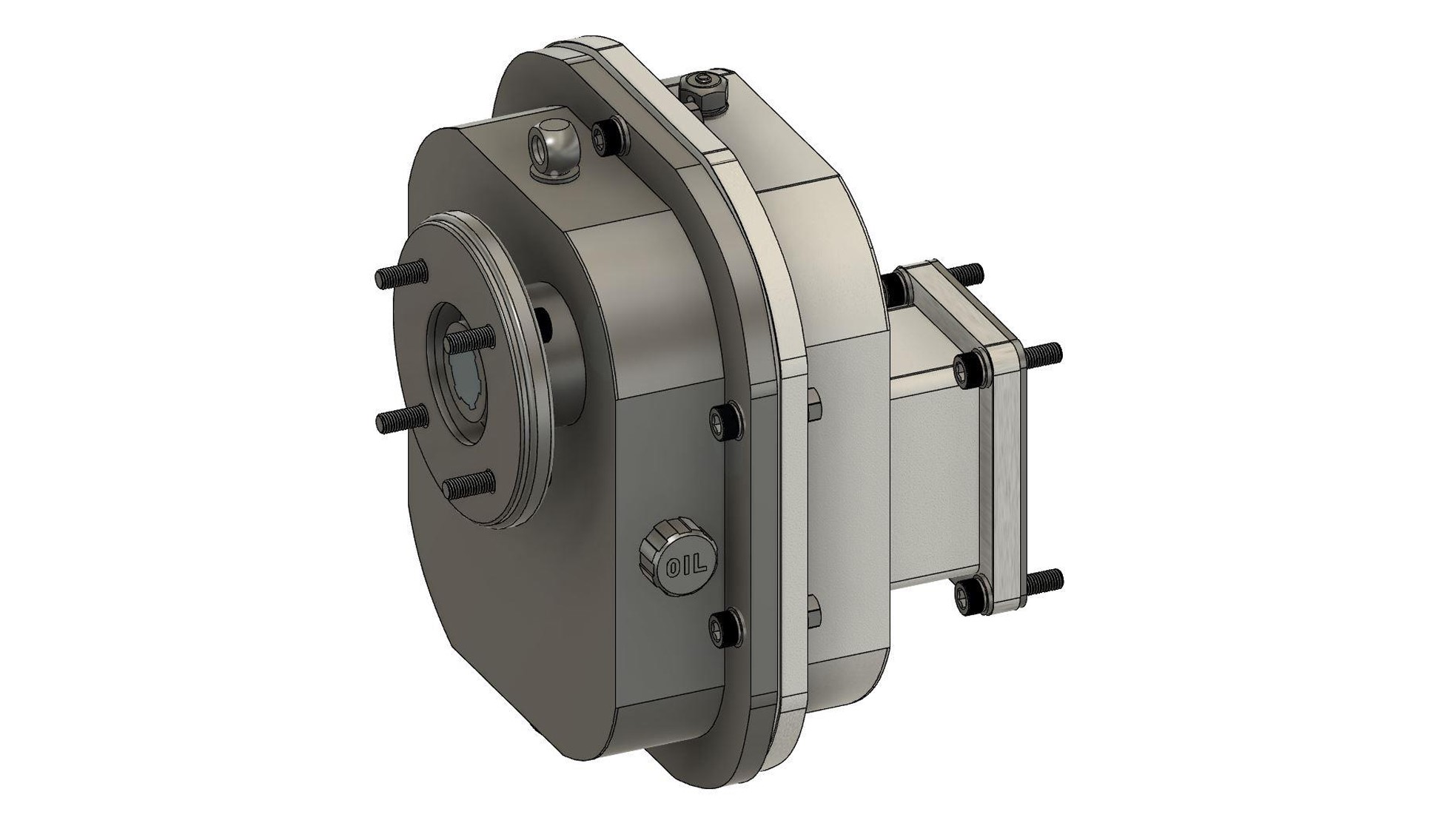
The following slides show the detailed assembly drawings of our PTO speed reduction unit, showcasing the precise design of each component and how they come together to ensure seamless functionality and durability
And there you have it—from initial sketches to fully assembled precision. We’ve tackled every challenge, and now, this PTO unit is ready to keep the wheels of industry turning smoothly!

What Next?

Download Files?

Read Again?

Another Project?